MIRROR CELL ASSEMBLY
The
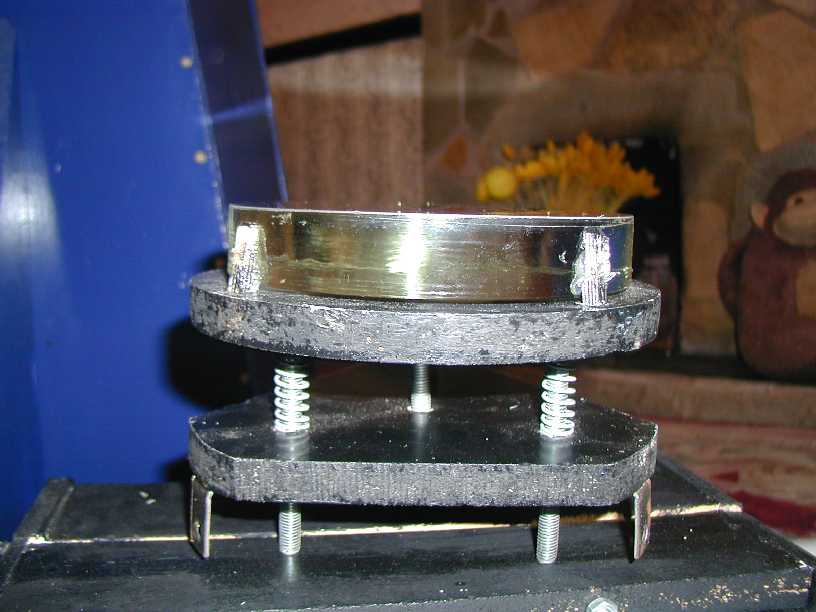
picture above shows the mirror cell assembly, it is composed of two main parts;
the base plate-which is bolted to the interior of the tube (you can see two
of the brackets)-and the top plate -which holds the mirror and can be aligned
using the spring loaded bolts.
Between
the exploded view below and the pictures above you should be able to work out
assembly details-top plate A has holes drilled for dowels (partly cut out) to
hold mirror-some depressions are part drilled in surface to accept silicon adhesive
to hold mirror in place-use a few nails between mirror base and plate A surface
to act as spacers. before this drill holes for dowels and to accept bolts-coutersink
so bolt heads are below surface and will not contact mirror-plate B has holes
for bolts -bigger dia than bolts to allow some free play- and a hole in centre
with a threaded insert put in-with mirror secured, place springs over bolts-put
on bottom plate, screw up nuts and you can see that with plate B secured in
scope that the mirror can be aligned by just turning the nuts (or wingnuts)
once aligned you screw a bolt into centre hole until it contacts plate A and
locks position
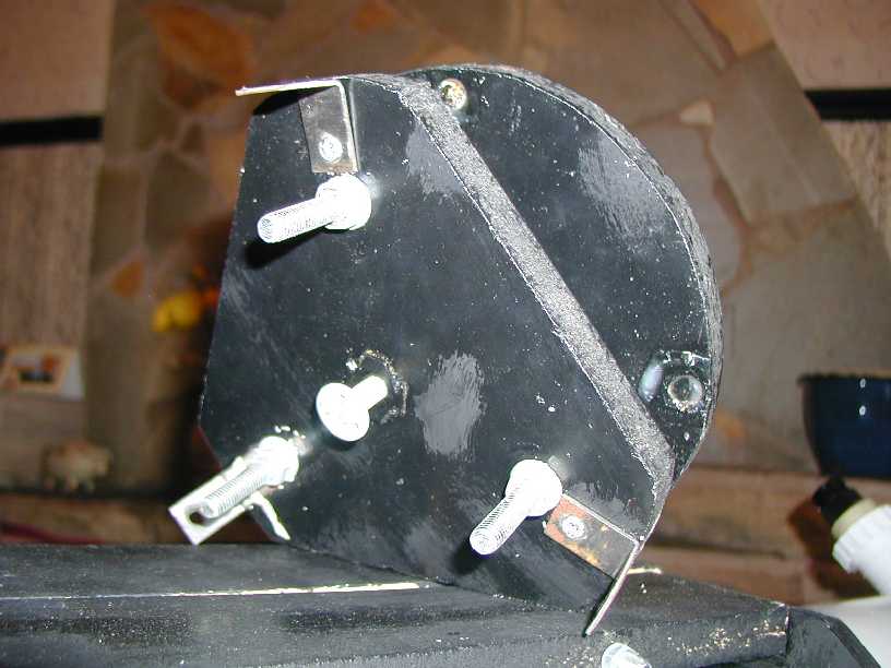
This
is a view from the base, you can see the 3 brackets for securing in tube, the
3 adjusting bolts and the central locking bolt. You can also see the dowels
which are used to hold the mirror in place in the top plate; from these views,
the following sketches and my technical description you should be able to build
this to suit your dimensional requirements.
Back to contents